Yong Heng Relay Install Help

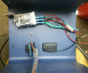
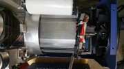
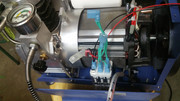
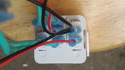
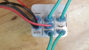
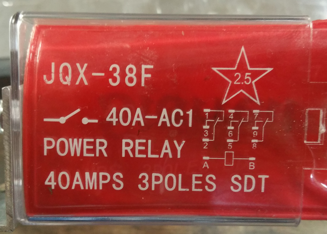
I have the basic 110v Yong Heng compressor that I want to upgrade to have the set pressure feature. I have the new version of their relay that comes with the wires attached and the dial pressure gauge. I have tried reaching out to YH for a schematic or directions on hooking up the relay but they have ignored me...Does anyone know of a schematic available or has the set pressure version? Thanks in advance!
 
This is the original connection of my Yong Heng which came with the auto shut off function. The circled pair of wires goes to the pressure gauge. Hope it helps.

1541228039_15008729075bdd46076be299.39857647_connect 1.jpg


1541228048_1205715435bdd4610d8ad53.44345192_connect 2.jpg

 
Post a picture of the control panel with the door open, typically the pressure switch will have normally closed contacts which open on rising pressure, thus interrupting the power to the contactor coil. Sometimes a relay is used because the pressure switch contacts can't handle the current needed by the main contactor to start the unit. Looking at the relay, A1 & A2 are for coil power with the other terminals changing state on energizing, usually relays are shown in a de-energized state, 11 & 12 are connected de-energized and 11 & 14 connect once energized, always check with a continuity meter..
 
The relay in your pic is different than the one in the previous post..

I cant see the relay config. however we can try this: o is a terminal, --------- wire

+ o--------o [press switch terminals] o---------o [coil A1]

120V

- o-----------------------------------------------------o [coil A2]

+ o--------o [relay] 11 o----motor [relay connection that connects when energized] 14 to motor [relay from above]

120v

- o---------o motor
 
Ok, this what we call a hot relay, its not the best way because it will fail with the compressor energized and will blow the disc...it needs to energize or change state to shut the motor off

'circuit closed when preset pressure is reached' that will change the state of the relay

your relay would need power at A & B to energize, the pics show no wires @ A & B

It appears to show your relay being used as a terminal strip, 1 & 2 are connected and dont change, [1 & 5 on the schematic]

8 & 9 are not connected, that would be the press switch to terminal to 6 & 8 on schematic?, 8 & 7 are connected per the relay config

Are the plugs with light green wires plugged int anything,? the way they are crimped 2 into 1 looks like they being used as jumpers ..