• *Effective 3/27/2024 - The discussion of the creation, fabrication, or modification of airgun moderators is prohibited. The discussion of any "adapters" used to convert an airgun moderator to a firearm silencer will result in immediate termination of the account.*

Porous Moderator Design Tests

Have the files.

Now to slice. Seem to be getting an unexpected internal perimeter, although I have set them to 0 in the slicer. I'll have to muck about with that to see what's causing this. Edit: Found out how to fix that.

ID is 28mm? Just confirming before sourcing CF tubing. Found some for $30.50 for 1 meter. Need to order before Chinese New Years, or it will be delayed a while.
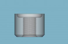
30mm x 28mm x 126mm nominal on the length. You can get 4 pieces out of a 500mm section if you hold your mouth right. You might have to scale it a bit in the slicer. 27.93 is just right for my purposes from my RESIN printer. Those caps are a tight fit. I use a jig I designed to pull the attachment end into place. It is a hard job without that tool. Threads on the attachment need to be chased out with a tap. I should have mentioned you will need a helicoil as well. MCMaster-Carr. They aren't cheap.
 
Last edited:
  • Like
Reactions: AirGunShooter
Currently shooting at a rubber mulch trap in a cardboard box. There's definitely a slap upon impact and it's noticeable outdoors. The shot is relatively quiet then the thwap some time later. An acoustic tunnel will definitely change the directionality of the sound, so that it is considerably less in directions say more than +/-20 degrees off axis, if the tunnel has some decent length. This is not to say that there won't be acoustic sidelobes, like an antenna, or diffraction, but it is a good start.

Indoors, well there is not as much delay to the target, since the distances are shorter. For indoor testing, I may make a replaceable end that I shoot through that is mounted on the trap itself. It all depends on how cheap this duct board is, and how I can get it home. Think it comes in 4x8 foot sheets and optionally longer. It comes in 1", 1.5" and 2" thicknesses. The thicker it is the more it attenuates low frequencies. How well it works for this "unconventional" application is totally unknown to me. I do know that plain pink fiberglass insulation if in a tube like form has pretty high attenuation, but I don't want to deal with trying to stuff it in sonotubes and being not rigid enough and requiring internal support. It would be a tough material to work with, although relatively cheap. The duct board is more rigid and designed to be made into ducts.
I have some insulated flex duct leftovers in the attic that could be used for this purpose. I might try a piece and see. Although not sure if it would be any less of a pain to setup/store. I've seen a few YT videos of people shooting in their basements where they just built a box to shoot through attached to their bench. Box was lined with carpet or similar materials.

Years ago, I had an apartment with a view onto a field... but the window only angled open a few inches. I did some surgical woodworking, so that one of the panes could be removed. This worked great until winter time. So I made a frame, covered it with cling film, replaced the glass pane with it and shot straight through it. Worked great, solved multiple issues (sound, heat loss) with no impact I could see on accuracy.
 
  • Like
Reactions: subscriber
I have some insulated flex duct leftovers in the attic that could be used for this purpose. I might try a piece and see. Although not sure if it would be any less of a pain to setup/store. I've seen a few YT videos of people shooting in their basements where they just built a box to shoot through attached to their bench. Box was lined with carpet or similar materials.

Years ago, I had an apartment with a view onto a field... but the window only angled open a few inches. I did some surgical woodworking, so that one of the panes could be removed. This worked great until winter time. So I made a frame, covered it with cling film, replaced the glass pane with it and shot straight through it. Worked great, solved multiple issues (sound, heat loss) with no impact I could see on accuracy.
We have flex duct in the house and some rigid larger diameter stuff for trunk lines. But no spares. It's not hard to build such a tunnel, but the whole thing is not so easy to store.
 
Helicoils themselves aren't that outrageous - it's the installer tool! (At least on McMaster.) What's the OD of the insert, 5/8-11 or 3/4-16?

No resin printer here. Just FDM. If I have to, I can make caps from aluminum, have a lathe. For the jig, is an arbor press sufficient? Have a 3T.
They are when you buy 25 at a time. ;)

You can make an insert tool out of a bolt and nut with a hack saw, a file and a vice. Chase out the printed threads with the tap a couple of times and insert the helicoil from the bottom of the attachment cap. Use your epoxy for a lubricant, just a drop, and the helicoil will stay wherever you leave it. Keep some denatured alcohol and paper towels handy for cleanup of epoxy. Scuff up both mating surfaces with 220 grit sand paper before glue up.

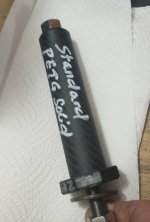
Regarding PETG as endcap material. I've had good luck with it. Use a variable layer height and print the top layers with ironing turned on. The variable layer height lets you use thick layers where you want strength and reliability and thin layers where you want it pretty. Once you are done printing it, if you want to add a bit of shine, work the ends over with 220, 400, and 600 grit wet/dry using alcohol as the lubricant. It will shine right up. Stick to layer height 0.20mm and below.

IMG_20240129_134424450.jpg
IMG_20240129_134624174~2.jpg
Link To The TAP Chart

You don't need to do all this unless you just want to do it. I will ship these to you the day after I am done collecting data (probably Wed). The TPU inserts are printed and the caps for those two are already tapped and gluing up in the CF. PETG 40% will be off the printer in an hour and both of those will be gluing up by sunset, I expect.
 
Last edited:
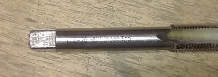
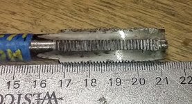
Hard to tell on the second tap, is that just a 1/2-20, or some other pitch? First one is 1/2-20 (1.27mm pitch).

Yep, buying supplies for a business, or a hobby/business can be quite expensive. For me it's just a hobby so I try to keep some of this on the cheap, simply because it's hard to amortize the cost with no income from sales. I made an electronic lead screw controller that I had offered for sale, had an amazing amount of inventory tied up with it, couldn't buy single quantities for a lot of items. The customer support for the product took an awful lot of my time. I'll support the existing ones, but I am not anxious to expand at all, not with a staff of one.

Did the slicing of various options. But it is not quite clear to me what they are. Perhaps you have already succinctly written them, but maybe I missed them. Are they:
PETG solid, PETG 40% gyroid (for what nozzle)
TPU solid, TPU 40% gyroid (for what nozzle size)

I recall in this thread you had determined a % infill which was for a particular nozzle width. Is the 40% gyroid infill for the 0.6mm nozzle?
 
Hard to tell on the second tap, is that just a 1/2-20, or some other pitch? First one is 1/2-20 (1.27mm pitch).
Both taps are 20 per inch. The helicoil is a wire coiled like a spring. It has no choice but to have the same pitch on the outside and the inside.
Yep, buying supplies for a business, or a hobby/business can be quite expensive. For me it's just a hobby so I try to keep some of this on the cheap, simply because it's hard to amortize the cost with no income from sales. I made an electronic lead screw controller that I had offered for sale, had an amazing amount of inventory tied up with it, couldn't buy single quantities for a lot of items. The customer support for the product took an awful lot of my time. I'll support the existing ones, but I am not anxious to expand at all, not with a staff of one.
Yeah my personal time line explains why I balked at taking orders. Eventually I might but I won't until I am comfortable that I can make a good moderator every single time and I have fully wrung out all the options WRT parts. For example helicoils are cheaper than EZ Taps but harder to get right. The jury is out on whether I will settle on the one or the other. I have a lot of 1/2 20 UNF helicoils so I am using them up. Once gone Ill have to decide.
Did the slicing of various options. But it is not quite clear to me what they are. Perhaps you have already succinctly written them, but maybe I missed them. Are they:
PETG solid, PETG 40% gyroid (for what nozzle)
TPU solid, TPU 40% gyroid (for what nozzle size)
Nozzle size is determined by your slicer. You'll be slicing those .stl files.
I recall in this thread you had determined a % infill which was for a particular nozzle width. Is the 40% gyroid infill for the 0.6mm nozzle?
Yes the infill tests were run using a 0.60 nozzle. That would likely make a difference if you compared a .40 print to a .60 print but you could decrease the 40% to 30% to compensate (some, not sure how much). I would think a 0.40 nozzle would make them more efficient even if they were printed at the same infill percentage. Apples to apples, if your going to print one with a .40 you'll need to print them all with that nozzle. You won't be able to compare them to mine but we might be able to make some inferences which are interesting if you went that way.

I have to caution you though. It is HARD to do these glue ups without the tool chain I had to make and there is a high probability you will wind up with some clipping. It is HARD to do these glue ups WITH the tool chain I had to make and I think I may have one already built which IS going to clip. Hope not but we will know tomorrow.


REGARDING THAT TOOL CHAIN:

I have a long 1/2 x 20 UNF bolt which threads through a traveler that fits inside the moderator tube. I can mount the tube on that traveler with the bolt through it and PULL the attachment cap into place once I have the helicoil installed. The purpose of that setup is to ensure as perfect as possible alignment between the attachment and the endcap on the other end of the moderator. Before I fine tuned the thread printing I used a different insert to hold the TAP square to the attachment when I was chasing out the threads. That tool has been eliminated by fine tuning the threads that I print. If I was you, I'd take my time about jumping on building those, but I am more than willing to help if you decide to go that route. PM me for my phone number if you need.

IMG_20240129_172622769.jpg
 
Last edited:
Good advice on making sure the threads are square. I usually start a tap in my lathe so everything is square and coaxial. If the threads aren't square, it's pretty much a guarantee that there will be clipping. Doesn't take much angular error to translate to clipping once magnified by the length of the moderator. A 0.1 degree error shifts the bore by 0.17mm out at 100mm.

I may try using my arbor press for this. There's enough gap in there to fit a whole (small) moderator. Have an insert in the ram which has been turned straight and the base is parallel with the insert. If that doesn't work, well I can get a bolt to pull the pieces together. Probably turn some custom washers on the lathe to ensure they are flat too. Most washers aren't very flat.
 
  • Like
Reactions: OldSpook
Good advice on making sure the threads are square. I usually start a tap in my lathe so everything is square and coaxial. If the threads aren't square, it's pretty much a guarantee that there will be clipping. Doesn't take much angular error to translate to clipping once magnified by the length of the moderator. A 0.1 degree error shifts the bore by 0.17mm out at 100mm.

I may try using my arbor press for this. There's enough gap in there to fit a whole (small) moderator. Have an insert in the ram which has been turned straight and the base is parallel with the insert. If that doesn't work, well I can get a bolt to pull the pieces together. Probably turn some custom washers on the lathe to ensure they are flat too. Most washers aren't very flat.
Ok,I'll stop worrying. All the printing was done by sunset but I decided to put off gluing up anymore inserts until tomorrow. I was getting ahead of the epoxy and that usually ends badly.

TPU appears to weigh quite a bit more than PETG and it exhibits more shrinkage.
 
Last edited:
Let's just call it being meticulous;) It's pretty clear you are meticulous in your approach and even your choice of materials. I looked up the epoxy, which is typically stocked at marine stores. Seems top shelf. How do you apply the adhesive to the the main stack? Or do you apply it to the CF tube? I'm thinking of thickness and uniformity, and wiping off the inevitable stuff that results from sliding stuff in tubing.

I printed a set in PETG as a test. Since I'm lazy I kept the nozzle at 0.4mm. So I did a 30% gyroid fill. If you hold the cylinder to the daylight and rotate it, occasionally one sees a flash of daylight all the way through. I've noticed that before. As printed it is coming out around 27.8-27.9mm in diameter for all the piece, which is close to the design in x & y. I need to check the z height, but it seems reasonable. First cone bore seems to measure around 8.1mm, but that was a cheesy caliper measurement not a careful one.

Getting excess squish on the first layer (excellent adhesion though) so your nice lettering "Airgun Only" is somewhat filled in. Not sure how to add z offset in this Prusa MK4, the controls are unlike what my MK3S+ had. But overall everything came out fine. Didn't do ironing, nothing fancy. Actually printed it in speed mode, just to see how it would turn out. Also just used uniform 0.2mm layers. I had turned the variable slicing on, looked at everything and decided against it. Haven't had trouble with 20 TPI threads at 0.2mm in standard or speed mode in the past, although I've always tapped them. The tap doesn't cut anything, it just slightly removes a little peach fuzz, which reduces insertion/threading torque. Made my own barrel adapters and the 1/2-20 threads are single pointed and measured to be nominal pitch diameter for 2A thread class. (Thread micrometer for the win!)

Don't know if this will work, but I will print a tube for this assembly to fit in. It won't be as nice or strong as CF, but it will be in hand. Who knows, it might collapse upon assembly! Worth a try though.
 
Ha ha, I can see why you glue these! Tried an assembled PETG LDC with a low power 2240. End cap came flying off and smacked the close by target trap. Hmm, I might design this temporary tube with threaded ends. I'd like to be able to just swap cores and see what happens. Would make it easier to experiment. I had originally designed the printed tube to be 28mm ID and 32mm OD. If 32mm, I can just fit it in a collet (which I did, just 10 minutes ago) and turn the LDC on a lathe. It helps debur the edges due to the brim. By the way, the arbor press was the balls. Just pressed everything in without a whole lot of effort.

How fine a thread can be printed in FDM?
 
  • Like
Reactions: OldSpook
@WobblyHand I've had success printing very fine threads with my printer. The AGT Vixen shroud uses M48x1.25mm thread. It's non-standard so I needed to manually specify it as an option in Fusion360 when I designed my own endcaps. The threads in my endcaps have survived repeated use and I haven't had a explosive unloading of my moderator's guts yet. The hardest part was tuning the threads so they had an appropriate amount of clearance. I had to go a bit looser than spec to get a good fit.

While I was getting the threads right, I tested a few held in with tape, and one evening I had an opportunity to dispatch a pest. I took the shot but this time the tape wasn't up to the task. No mouse fart, I woke everyone up in the house with a huge booming echo as the moderator internals shot down range.
 
  • Haha
Reactions: HogKiller
@WobblyHand I've had success printing very fine threads with my printer. The AGT Vixen shroud uses M48x1.25mm thread. It's non-standard so I needed to manually specify it as an option in Fusion360 when I designed my own endcaps. The threads in my endcaps have survived repeated use and I haven't had a explosive unloading of my moderator's guts yet. The hardest part was tuning the threads so they had an appropriate amount of clearance. I had to go a bit looser than spec to get a good fit.

While I was getting the threads right, I tested a few held in with tape, and one evening I had an opportunity to dispatch a pest. I took the shot but this time the tape wasn't up to the task. No mouse fart, I woke everyone up in the house with a huge booming echo as the moderator internals shot down range.
Destructive testing, my favorite.
 
@WobblyHand I've had success printing very fine threads with my printer. The AGT Vixen shroud uses M48x1.25mm thread. It's non-standard so I needed to manually specify it as an option in Fusion360 when I designed my own endcaps. The threads in my endcaps have survived repeated use and I haven't had a explosive unloading of my moderator's guts yet. The hardest part was tuning the threads so they had an appropriate amount of clearance. I had to go a bit looser than spec to get a good fit.

While I was getting the threads right, I tested a few held in with tape, and one evening I had an opportunity to dispatch a pest. I took the shot but this time the tape wasn't up to the task. No mouse fart, I woke everyone up in the house with a huge booming echo as the moderator internals shot down range.
I have printed 1.27mm threads, which is 20 TPI, using 0.2mm layers, or about 6 layers per thread I'm thinking of 32 TPI which is 0.794 mm pitch. If I print with 0.1mm layers in the thread region, that gives about 8 layers per thread. I'll use variable layers, and hopefully not take a beating on the rest of the part. The 20 TPI threads only require a minor chasing to be serviceable, the 1/2-20 tap only removes a minuscule amount.

Yeah, I had the rapid disassembly myself! Was a bit surprised at first, but was laughing afterwards. I wasn't sure it would hold at all, and it didn't.
 
Ha ha, I can see why you glue these! Tried an assembled PETG LDC with a low power 2240. End cap came flying off and smacked the close by target trap. Hmm, I might design this temporary tube with threaded ends. I'd like to be able to just swap cores and see what happens. Would make it easier to experiment. I had originally designed the printed tube to be 28mm ID and 32mm OD. If 32mm, I can just fit it in a collet (which I did, just 10 minutes ago) and turn the LDC on a lathe. It helps debur the edges due to the brim. By the way, the arbor press was the balls. Just pressed everything in without a whole lot of effort.

How fine a thread can be printed in FDM?
How about a ping pong ball launcher?

How fine a thread? I'd have to venture not less than 3 times the layer height?
 
  • Like
Reactions: denovich
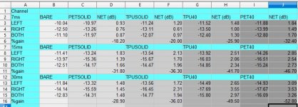
Well I'm done testing and my results are "mixed" but I think pretty "legit".
Rankings.jpg
I think the best way to summarize my results is this chart.

EDIT: This chart is the result of taking three shots with each moderator while recording at 44100 Hz. The resulting file was imported into Audacity and the samples were cut out for the duration shown in the left column starting at the "uncorking" of the moderator and extending in the time domain for the number of milliseconds shown. Why? The shot event is well and truly completed by 7 ms after the uncorking. I proved this for myself by starting with a 15ms and 30ms sample set and then doing a binary search until I found the sample duration which gave me the highest RMS reading (7ms). Even one ms more/less than that reduced the average RMS. I saved the other data to show proof of that assertion. The longer you record after the shot the lower the RMS value will be because RMS is averaged over time. If you find the highest sample "window" after the uncorking you have encapsulated the entire shot noise you can influence with the addition of a moderator... Well this is my logic anyway :ROFLMAO:

Starting left to right loudest to most quiet with net dB and percent delta for both channels. I have shown left and right but all that matters is the result for both channels.
  • TLDR?
  • Gyroid is better than Solid in both cases.
  • PET beats TPU when Gyroid is used, more data MIGHT change that.
  • PETG is something like 10% lighter than TPU
That's really it in a nutshell. I (personally) am going to switch back to PETG and use Gyroid at 40% until I am comfortable that I have solved any accuracy problems which may/may not have cropped up. Tom tells me that the current TPU Gyroid version of the "Ember" design is not "competition" ready. He says, "It is head shots only squirrel hunting ready." That's OK but not good enough for either of us so I'll be working that problem going forward. Also it is easier to print gyroid accurately in PETG and so I can run my BORE a mm tighter. That will further impact performance of the moderator.

I have attached the raw data for your enjoyment. That file is half a gig and I will delete it before COB today so if you want it you better get it now. I don't like to leave big stuff on Mike's server(s).

View attachment 430525
 
Last edited:
Let's just call it being meticulous;) It's pretty clear you are meticulous in your approach and even your choice of materials. I looked up the epoxy, which is typically stocked at marine stores. Seems top shelf. How do you apply the adhesive to the the main stack? Or do you apply it to the CF tube? I'm thinking of thickness and uniformity, and wiping off the inevitable stuff that results from sliding stuff in tubing.

I keep denatured alcohol handy in gallon cans... :p. It depends upon my intended power level. I wash the parts to be glued down with a paper towel soaked in alcohol. I keep that in a spray bottle. Once they are clean I'll scuff all mating surfaces good with 220 grit wet/dry and clean them again. Then I apply a very thin layer of West System to all surfaces and press fit them. If they need to be held in clamps I'll wipe them down after assembly with another towel soaked in alcohol. Then I put them in the clamps or under the weights as appropriate. Buy a box of nitrile gloves. You are going to want them.
I printed a set in PETG as a test. Since I'm lazy I kept the nozzle at 0.4mm. So I did a 30% gyroid fill. If you hold the cylinder to the daylight and rotate it, occasionally one sees a flash of daylight all the way through. I've noticed that before. As printed it is coming out around 27.8-27.9mm in diameter for all the piece, which is close to the design in x & y. I need to check the z height, but it seems reasonable. First cone bore seems to measure around 8.1mm, but that was a cheesy caliper measurement not a careful one.
Should be ~8.6 on the bore and ~7.6 on the end cap. You might need to do a little sanding on that core to get it to fit, I had to.
Getting excess squish on the first layer (excellent adhesion though) so your nice lettering "Airgun Only" is somewhat filled in. Not sure how to add z offset in this Prusa MK4, the controls are unlike what my MK3S+ had.
"First layer height" in Prusa slicer will let you set it lower. So if you are tight and using .20 use .10 for your first layer and #2 will start at 0.10. Then a bit of wet/dry and you have nice clean ends (as good as ironing).
But overall everything came out fine. Didn't do ironing, nothing fancy. Actually printed it in speed mode, just to see how it would turn out. Also just used uniform 0.2mm layers. I had turned the variable slicing on, looked at everything and decided against it. Haven't had trouble with 20 TPI threads at 0.2mm in standard or speed mode in the past, although I've always tapped them. The tap doesn't cut anything, it just slightly removes a little peach fuzz, which reduces insertion/threading torque. Made my own barrel adapters and the 1/2-20 threads are single pointed and measured to be nominal pitch diameter for 2A thread class. (Thread micrometer for the win!)

Don't know if this will work, but I will print a tube for this assembly to fit in. It won't be as nice or strong as CF, but it will be in hand. Who knows, it might collapse upon assembly! Worth a try though.
You should be able to print a tube without issues. Go with a thickness that is 0.3666 times the caliber. That will hold about anything you will put through it.
 
I had chosen 2mm walls for the tube. Your calculation came out to 2.02mm for 0.22cal. Close enough!

Attempted to print some fine threads, yeah that's a trick in FDM. 32 TPI is not bad, which is amazing. Used 0.1mm layer height for them.

Downloaded all the data. Thanks.
Man! Deciding just exactly where to grab the start of a sample (spotting the uncorking) is HARD without that LASER switch Stan is using! Just whipping my butt here today.

I have just about concluded the lack of a proper triggering device requires deeper statistical analysis unless you just want relational (ranking) data. It is pretty easy to measure them well enough to rank them in order of performance WRT quieting but it's a whole lot harder to get repeatable quantitative data without a deterministic starting point in the shot cycle.

I have shot the end out of one of the glue ups and am going to have to print another endcap. Tomorrow I have to do range safety officer so that day is a down day. I'll get these in the mail by Friday. Word.
 
Last edited: