• *Effective 3/27/2024 - The discussion of the creation, fabrication, or modification of airgun moderators is prohibited. The discussion of any "adapters" used to convert an airgun moderator to a firearm silencer will result in immediate termination of the account.*

Porous Moderator Design Tests

Have not done a quantitative test yet, but a qualitative test doesn't reveal a huge difference (by ear) between a PETG or TPU gyroid stack. It takes a bit to swap cores, so I am wondering about the wisdom of my choice to make a system that threads together. It's not terribly hard to swap cores but it takes a few minutes. Printing a new tube doesn't take all that long. A nice multi-start thread would reduce the assembly problem, but I don't want to mess with that right now.

But this thread is about quantitative results, so I think I may print up some more parts, so I can audio test the pieces in a relatively short time.
 
According to https://bitfab.io/blog/3d-printing-materials-densities/ the density of PETG is slightly greater than TPU. My 30% gyroid PETG stack weighs 235 grains, and the 30% gyroid TPU stack weighs 229 grains, which is somewhat close to what the link states. It will be an hour or two before I can weigh the solid TPU stack. The TPU gyroid stack is squishable, when I put these together I need to measure the total length of the moderators, since I don't want to compress or distort the TPU. Lots of details to be sure.
 
@OldSpook "muffing the experiment" was not meant to be personal. I've done, perhaps like you, a lot of field trials collecting data, and sometimes things don't work out when you bring the data back to the lab. But to be specific, I opened the TPUSOLID wav file, and used the Analyze > Find Clipping command with Start and Stop thresholds of 3 samples. Out of 6 recordings, (3 shots and 2 channels) 3 are clipped. Initially, I simply used Show Clipping in Waveform, because I didn't even know about the Find Clipping command which allows changing how many samples. In Audacity, I'm a novice user, hardly know the tool enough to drive it.
View attachment 430717
All I know is, if a single sample is +1 or -1, I suspect clipping. We could argue about percentages and all, or the significance, but if we want unassailable quantitative measurements, we need to not clip. Hard to argue model X is better than Y if both sets of numbers have unknown errors in them, at least that's how I see it. Perhaps you have access to data that is high fidelity and not clipped and can make a good argument, that the error is bounded by n dB. I haven't seen such a study, so don't have anything to work with.

This stuff is hard to do. If it was easy, anyone could do it. Most of the comparisons I've seen just don't match up with other comparisons. Maybe it's because in each experiment there is an unknown error due to clipping...
Back on this.
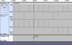
twoandahalftenthousandths.jpg

This slice is 2.5 TEN THOUSANDTHS of a second. It shows the single data point which is clipping. There are three such data points in the entire sample. If all three were in the same shot sample and you trimmed that sample to 10 ms, how loud (what sound level would they have to be) to alter the result significantly?

Tomorrow I am going to do the test again. I am going to set my sampling software "Parrot" to attenuate the signal by -10 dB and change the sampling location to be ten yards down range and at about 1 o'clock (so 30 degrees clockwise). If that clips I will set the attenuation to -20 dB and continue the process until I have eliminated clipping. I don't like throwing away data either and adding attenuation "feels" like that to me.

Will I loose more information by allowing those three clipped points or attenuating the entire sample by -20 dB?
 
According to https://bitfab.io/blog/3d-printing-materials-densities/ the density of PETG is slightly greater than TPU. My 30% gyroid PETG stack weighs 235 grains, and the 30% gyroid TPU stack weighs 229 grains, which is somewhat close to what the link states. It will be an hour or two before I can weigh the solid TPU stack. The TPU gyroid stack is squishable, when I put these together I need to measure the total length of the moderators, since I don't want to compress or distort the TPU. Lots of details to be sure.
That's odd. Maybe different brands of TPU are enough different that this is going to be one of those "depends" moments when one maker's TPU is lighter than another maker's PETG, etc... I don't know if I reported my actual weights but I found the opposite when I weighed my stacks. Either way it isn't that much. It isn't as much as I thought it was going to be when I wrote the comment.
 
Back on this.
View attachment 431141

This slice is 2.5 TEN THOUSANDTHS of a second. It shows the single data point which is clipping. There are three such data points in the entire sample. If all three were in the same shot sample and you trimmed that sample to 10 ms, how loud (what sound level would they have to be) to alter the result significantly?

Tomorrow I am going to do the test again. I am going to set my sampling software "Parrot" to attenuate the signal by -10 dB and change the sampling location to be ten yards down range and at about 1 o'clock (so 30 degrees clockwise). If that clips I will set the attenuation to -20 dB and continue the process until I have eliminated clipping. I don't like throwing away data either and adding attenuation "feels" like that to me.

Will I loose more information by allowing those three clipped points or attenuating the entire sample by -20 dB?
I see your point, but do we actually know how high the point was originally? We don't yet. The information is lost forever. If you clip at 10 dB and 20 dB, then something is definitely weird. Too much attenuation is bad too. Let you know why in a paragraph or two.

It's one of life's unfortunate trade offs when sampling impulsive stuff, do we give up the top end or the bottom end? Impulsive signals are really hard, because they require transducers with good dynamic range. My IMM-6 microphone has 70dB dynamic range, for what it is worth. Do you know what your microphone dynamic range is? Maybe I will run into the same problem.

But remember the old radar guy's trick. (That's me, if you couldn't figure it out.)

As long as the microphone can still detect the background noise (so you see bits twiddling during the inter shot period) and not clip, you can recover the information. The "signal" may look like junk in the time domain, but we can get the spectra simply because of the process gain of the FFT. A 16K FFT has 10*log10(16,384) = 42dB of process gain in every bin. So we could easily recover stuff that had a -20 dB SNR in the time domain, but it would show up as +22dB SNR in the time domain. If we need more process gain, we need to use a longer FFT.

The idea is to back off in distance from the source until we don't clip for the loudest object we wish to use as a reference, be it a bare shot, or a reference LDC. It's not good to use an attenuator, because it is possible attenuate the microphone noise below that of the least significant bit of the ADC. But it is ok to use an attenuator to see how much attenuation is needed to not clip. But then one should back away from the source the distance corresponding to that attenuation and remove the attenuator. The sound should drop off as 1/(r^2) or -6 dB for every doubling of the range. Radar drops off at -12 dB for doubling of the range since the return is 1/(r^4). So if the mic is at 5m, setting the mic at 10m will result in 6dB attenuation from whatever it was at 5m. All we need to do is make sure we don't clip. Then we get to the next important thing.

We want microphone noise, more specifically, noise that the microphone hears in the background to be no less than 1.4 bits RMS of the ADC bits. If that is possible, full signal recovery is possible, to the extent of the FFT gain. Sorry to be so technical, but this works. I've used this in in military and commercial applications, including automotive radars at 24 & 77 GHz. My company sold 10's of millions of automotive radars a year. My designs had runs of over several million.

Systems that are developed to measure gunshot noise (for characterizing range hearing safety) use very high end equipment. I looked into one and it was very expensive. Now we don't have to measure sounds quite that loud, but we are facing similar tough constraints. They use special microphones and sophisticated signal processing. They also sample sound at a minimum of 200KHz, per MIL standard. That's because ultrasonic sound can still be damaging, even though we do not perceive it. Just getting a wide band calibrated mic 20 Hz to 100 KHz is a trick. My mic is calibrated from 20Hz to 20KHz. It falls off a cliff at 20KHz. Costs a bunch of $$$ to get that full bandwidth. We are attempting to do the "poor mans" version, for the purpose of reducing neighborly attaction, ire, or just trying to preserve what hearing we have left.

Just reiterating, this measurement isn't a trivial task, but I do think it is doable with some ingenuity and motivation.
That's quite a resume you have there.

When I was in the military I taught Electronic Warfare at the Joint Service Cryptologic Center and School in San Angelo Texas.

We BOTH understand the problem we are trying to solve. I'm not going to ask you to use the data you already have and the data that I will get for you to prove that I didn't waste my time collecting more data. That would be a waste of YOUR time. But I will welcome the effort if you attempt to try it. 😉

Oh yeah and if we are worrying about details which are down in the noise that number is not 1.4 bits RMS it is 1.414213562 non repeating bits RMS. Perhaps we should replace that with 2^(1/2) bits RMS but then we would ALWAYS be throwing away data so we might as well just GIVE UP because that means the perfect answer might be expressed but it can never be measured, wouldn't it?

You can disregard that rant... I'm tired and it's down in the noise. 🤦‍♂️
 
Last edited:
That's quite a resume you have there.

When I was in the military I taught Electronic Warfare at the Joint Service Cryptologic Center and School in San Angelo Texas.

We BOTH understand the problem we are trying to solve. I'm not going to ask you to use the data you already have and the data that I will get for you to prove that I didn't waste my time collecting more data. That would be a waste of YOUR time. But I will welcome the effort if you attempt to try it. 😉

Oh yeah and if we are worrying about details which are down in the noise that number is not 1.4 bits RMS it is 1.414213562 non repeating bits RMS. Perhaps we should replace that with 2^(1/2) bits RMS but then we would ALWAYS be throwing away data so we might as well just GIVE UP because that means the perfect answer might be expressed but it can never be measured, wouldn't it?

You can disregard that rant... I'm tired and it's down in the noise. 🤦‍♂️
We're cool. I plugged my ears. :LOL:

Have done some ECM work and was an Old Crow for a while, and did some SIGINT for some special platforms. Designed some interesting capture boards for SIGINT analysis. But most of my career has been in radar systems, from customer requirements, form fit and function, and antennas, all the way through signal processing, detection and some feature extraction.

All that aside, the posted data sets have some good data. Perhaps we can develop some heuristics to "restore" the clipped data based on some unclipped data sets. Generally we don't like to do this since there can be a large error bar associated with this. The idea would be to examine unclipped data and see if there were some general relationships between sections of the waveform, sort of a signature analysis. To be meaningful, however, that would require a lot of data, and that is not so easy to acquire. Which was why I was strongly suggesting to not clip, even at the expense of the data appearing to contain nothing. A lot of the signal is still available, it is just under the unprocessed noise floor. Sometimes it is not as bad as it looks.

However, there are times when one just cannot extract the data, unless the front end is improved. (Special microphones, better preamps and audio chain, all the way up to the ADC.) At least in the radar world, I would start with what the requirements were (usually customer driven) and then derive the system that would do the job. These system derived requirements were flowed down to subsystem requirements and supplied to designers. For small jobs, sometimes the designer was me. Not quite sure how to do this with this class signal to be honest, but I'd think the process would be similar.

The real world, as you well know, is often uncooperative with our efforts. We get clipping, less than ideal measurement environments, less than perfect instrumentation, and have to muddle through it all.

Just thinking out loud, if the microphone has 70dB dynamic range, we'd like the front end noise (audio noise) twinkling the LSBs and the peak signal to be just under the peak capability of the mic, say at 68 or 69 dB. The audio noise that the mic picks up should be invariant to the distance from the muzzle, because it is just audio background noise. So one would adjust the distance from the mic to the source to reliably get values under 70 dB. From that point on, with that AG, at that tune, that would be the measurement distance for the tests. As a note, there is a difference between the microphone noise and ADC noise. It is essential for signal recovery, that the microphone noise is about ~10dB greater than the ADC noise. Any more, and one is wasting dynamic range (but we still can extract the signal with processing, but with lower SNR), any less, it rapidly gets to be difficult to extract the signal at all. My two cents. If we basically follow this general approach, we can recover the best representation of the waveform, with the least errors (which are dependent on SNR).
 
Yikes! I am glad you guys know how to get a high signal to noise ratio. It gets tricky when the (airgun) noise is the signal :)

The closest I got to radar was synthetic aperture radar. I did not work on or with the radar itself; only the structure that carried it; and the vehicle that was to put that payload into LEO.
If one is trying to measure the total energy, with the least error, we need to measure ALL of the signal with the highest possible SNR. It is a well known fact that the estimation error variance of any extractable parameter is proportional to 1/SNR.

If we are arguing about 10's of dB's it doesn't matter one bit. If we expect to compare units that vary by 0.5-2 dB (we ARE trying to do that it seems) then SNR matters a lot. There can be a lot of energy contained in long decay tails of a signal which tends to be low SNR. Estimation error can be many, many dBs at low SNR's, and 0.01dB at high SNR's. I used to extract angle of arrival from radars and it was extremely sensitive to SNR, much more so than simple detection. We needed at least 10 dB more SNR to measure angle than for detection. Anyways, nearly 99.9% of the time, it is good to have high SNR measurements. If nothing else, high SNR systems have more margin, perform better (lower errors) and become robust against degradations.

SAR is neat stuff. Super long virtual antennas yield very high resolution. The outputs are nearly photographic quality in all weather.
 
Last edited:
FYI, one can measure the ADC noise roughly by putting in a resistor with the same impedance as the microphone across the ADC (audio) input. This is assuming we haven't played with gain settings. We can compare the noise of the resistor to the microphone noise. We want to be able to see the noise rise due to the mic. The output impedance of the IMM-6 is 200 ohms. I just ordered a TRRS adapter ( like https://www.amazon.com/Cerrxian-Ter..._1_9?keywords=trrs+plug&qid=1706886001&sr=8-9 ) so I can install a 200 ohm resistor across the microphone input. The resistor would establish the baseline noise of the capture equipment. At the same gain setting, the mic should result in a noise rise over the resistor. Ideally, about 10dB more.
 
@OldSpook "muffing the experiment" was not meant to be personal. I've done, perhaps like you, a lot of field trials collecting data, and sometimes things don't work out when you bring the data back to the lab. But to be specific, I opened the TPUSOLID wav file, and used the Analyze > Find Clipping command with Start and Stop thresholds of 3 samples. Out of 6 recordings, (3 shots and 2 channels) 3 are clipped. Initially, I simply used Show Clipping in Waveform, because I didn't even know about the Find Clipping command which allows changing how many samples. In Audacity, I'm a novice user, hardly know the tool enough to drive it.
View attachment 430717
All I know is, if a single sample is +1 or -1, I suspect clipping.
I couldn't help but notice, your file description says it is a 32 bit float file. It isn't, clearly. 32 bit sound files have over 1,500 db of headroom, 24 bit files are around 145 ish db headroom, I forget what 16 bit files are, except trash. Audacity displays files you open based on what your preferences are set and when opening an 8bit,16bit,or 24 bit file in 32 bit float, it is amplifying the source to be the same db down from 0 DBFS and it dithers/whatever the sample rate to whatever your preference is set, which is 44khz in your example. A 1500db sound would turn your body into extremely thin ooze spread all over the place, nothing but liquid. In other words, that file is highly processed by Audacity just by opening it with your preferences, or it's possible whatever you recorded with saves the files as 32bit, which unless you have 10's of thousands in equipment, it isn't. If your recording saves as 32 bit, it is doing a lot of processing to show your file like that.

High end sound recordings are done in 32 bit allowing no extra amplification of mics/etc. which also amplifies noise. Post processing/mixing then deals with as pure of sound as technology so far allows recording.
 
As promised ZERO clipping in the moderator samples, zero attenuation.

Sensor is at 33 feet, 11 o'clock (33 degrees CCW) relative to direction to target and 4 inches AGL in a wet, grassy field.
There is a lot of data here. Each cut is a different moderator.

View attachment drive-download-20240202T163253Z-001.zip

@karl_h thank you very much that may be part of the problem we're having. I do not know that my device is actually sampling at 32 bits. Sounds a lot like it probably isn't I hope that it is at least 24 bits but we both know that's unlikely also. Thank you very much for the information.
 
Last edited:
I couldn't help but notice, your file description says it is a 32 bit float file. It isn't, clearly. 32 bit sound files have over 1,500 db of headroom, 24 bit files are around 145 ish db headroom, I forget what 16 bit files are, except trash. Audacity displays files you open based on what your preferences are set and when opening an 8bit,16bit,or 24 bit file in 32 bit float, it is amplifying the source to be the same db down from 0 DBFS and it dithers/whatever the sample rate to whatever your preference is set, which is 44khz in your example. A 1500db sound would turn your body into extremely thin ooze spread all over the place, nothing but liquid. In other words, that file is highly processed by Audacity just by opening it with your preferences, or it's possible whatever you recorded with saves the files as 32bit, which unless you have 10's of thousands in equipment, it isn't. If your recording saves as 32 bit, it is doing a lot of processing to show your file like that.

High end sound recordings are done in 32 bit allowing no extra amplification of mics/etc. which also amplifies noise. Post processing/mixing then deals with as pure of sound as technology so far allows recording.
The values in the files are floats. But the ADC on my computer is only 16 bits. + 15 bits positive, and 15 bits negative. Not it's not high fidelity audio, it's commodity grade. So one bit above zero is stored as 1/(2**15) = 3.0517578125e-05, which is a floating point number.
 
As promised ZERO clipping in the moderator samples, zero attenuation.

Sensor is at 33 feet, 11 o'clock (33 degrees CCW) relative to direction to target and 4 inches AGL in a wet, grassy field.
There is a lot of data here. Each cut is a different moderator.

View attachment 431386
Thanks. Downloaded. FYI, the other thread has some reduced data showing time and frequency domain responses. Learned a bit to more systematically extract the shots. Looking forward to it.
 
  • Like
Reactions: OldSpook
Results if these are wrong please let me know. Sparse data has a way of leading to marginal conclusions.

I collected 5 shots for each unit below:
  • Bare Rifle
  • TPU Solid
  • TPU Gyroid 40%
  • PETG Solid
  • PETG Gyroid 40%
I collected the audio from 31 feet at 32 degrees counter clockwise from (left of) the line of fire. There are a number of shots which show the signature of the pellet striking a cinder block at about 202ms after the uncorking event. This may be useful for indexing one sample against another when comparing individual shots. In the future I am going to run the test while shooting into the backstop because it finitely bounds the data and gives me an index point which is independent of the moderator data (unless the moderator changes the muzzle velocity, haven't seen that yet).

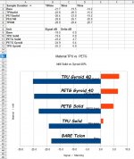
I sampled each shot starting with the uncorking for durations of 10ms, 50ms and 100ms. I aggregated that data as one sample and computed the RMS level for the group ( a fancy way of saying I averaged the samples in Audacity ). The resulting average for each set of duration was then computed and placed in the spread sheet you see below. Once I had collected and averaged the data for each duration, I again averaged those to get an "average" performance. That is also shown in the image from the spread sheet.

At that point I created the graph and plotted the data in rank order. The Gyroid infill out performs the solid infill in both tests again. The TPU out performs the PETG when Gyroid infill is used by half a dB (this might change with more measurements) and the PETG out performed the TPU when solid infill was used. I would not expect that to change because I ran the test twice thinking I had got it wrong the first time.

What would I recommend? If my boss were asking me I'd tell him I need to do more testing, but he isn't. Since I am my own boss I am going to use PETG and GYROID at 37% infill in future moderators because it obviously performs comparably well and I can print it with less stringing and more precision. That will allow me to use a smaller bore which in turn will improve it's performance slightly.

One thing I need to study is the change in accuracy when using Gyroid infill Tom reports that it is accurate enough for "head shots only" squirrel hunting but it is not accurate enough for competition. That is a non-starter for both of us so our next efforts will be pointed at finding out what infill percentage gives us match accuracy. Those tests may even eliminate the gyroid infill from use entirely, but I think we will get it.

Sincerely, guys, if your numbers disagree with this data enough to change the order I ranked these in, please call me out on it publicly BECAUSE there are other guys who would want to know and it might convince me to change my mind and switch back to TPU as well.

Thanks for the opportunity to serve.
Mike

result.jpg

View attachment data.zip
 
Last edited:
  • Like
Reactions: BlackICE
I meant only that I wasn't going to use TPU for printing a moderator. I have used the stuff to make a butt pad and "rubber" stopper for a salt shaker. If I don't need the properties of TPU I would use something else. The stuff prints slower and strings more than PLA or PETG. PETG strings more than PLA and overhangs and bridges are harder to do. However PETG withstands higher temperatures and better impact strength and with your data better sound deadening.

For most people I think PETG is the way to go. If you use PLA and go shooting on a hot day in the sun it may deform. You can anneal the PLA to get better temperature resistance but it will probably distort the dimensions. I had a button I printed for an oven with PLA it deform badly when I used the oven to 450F. I printed a new part and annealed it buried salt at 210F for 1 hour. After that you can put it in boiling water without it going soft! The dimension changed less than 1.5%. That would not be the case for a moderator with cones inside!

One theory is material with a higher density would better attenuate sound. If that is so then nylon or FPE may be worth a try. I'm guessing FPE would be the way to go.


MaterialDensity [g/cm3]
PLA1.24
ABS1.04
PETG1.27
NYLON1.52
Flexible (TPU)1.21
Polycarbonate (PC)1.3
Wood1.28
Carbon FIber1.3
PC/ABS1.19
HIPS1.03
PVA1.23
ASA1.05
Polypropylene (PP)0.9
Acetal (POM)1.4
PMMA1.18
Semi flexible (FPE)2.16
 
Last edited:
  • Love
Reactions: OldSpook