Huben Huben GK1 .22: A Beginner's Journey to a DIY Mini Carbine

i finally got my GK1 converted to a Carbine (or whatever one wants to call it), installed a folding stock & loading gate from Moistone ,a special mod(from elsewhere) to have clearance room for my discovery scope, & sighted it in , ran 3 mags through it (i was shooting at the side of a junk caddy, no targets , just shooting at were the pellets were hitting, JSB 18's 22 cal & rain came stopped the fun, anyway i think all of my other A/gun's will not be used for a long time if at all , maybe even sold . i have some A/G's that are too nice for me to take out back in my junkyard to shoot in fear of damaging them , so all i have been shooting since last year is my Notos , as i wasn't worried about a scratch, don't want to scratch the GK1 either , but it is going to be used anyway , sorry for the rambling on , i have a sinus headache, & the sun is shining , going to go shoot my new Toy, i can not Recomend the GK1 ENOUGH , just buy one you will see.
 
  • Like
Reactions: Bandito and Wauzoo
I would love to be able to machine aluminum, but you use the tools you got!


2 problems with my standoff plan, regarding the standoffs themselves:

  1. I could only find hex standoffs. Solution: sand down the hex profile
  2. I need a way to back the standoffs off, should I ever want to remove them to disassemble the pistol. If enough of the hex profile stands proud, you could squeeze a hex wrench on there. But I didn’t really want super big screw head sticking out. Instead I planned on a grinding in a slot on the hex head, that way you can drive it in or back it out with a large flat head screw driver.


Standoff plan.jpg
 
I had considered a stand-off type approach when making my stock adapter. I’m certain it will work but since my adapter is machined aluminum, I really didn’t need it.

Fwiw, I don’t think you will need it either with a full infill print. The force, while significant, is buffered by a spring/buffer. Meaning that it’s not as shock loaded as it seams.

Keep in mind when changing hardware that the gk uses alloy screws here which may be significantly stronger than some of the standoff screws that are available.

Dave
I agree with Dave in that there is not really much "hammer" action going on with a solid print imo.
Of course, aluminum would be the best material for many reasons, including, withstanding the amount of cantilever forces that could be applied via a long lever=stock!
Dave, did you make your own aluminum one, or purchase?
 
  • Like
Reactions: Bandito
I agree with Dave in that there is not really much "hammer" action going on with a solid print imo.
Of course, aluminum would be the best material for many reasons, including, withstanding the amount of cantilever forces that could be applied via a long lever=stock!
Dave, did you make your own aluminum one, or purchase?
I made mine but mine includes an entire grip frame that changes some grip geometry and allows the use of ar style grip options.

Dave
 
I made mine but mine includes an entire grip frame that changes some grip geometry and allows the use of ar style grip options.

Dave
Gotcha, that's cool!
I'm comfortable with the factory grip and geo, and really like the adapter by MoistOnes, but am waiting for an aluminum to become available, just to have.

Have fun
 
I just mounted the huben3dparts.com rear picatinny mount and the carbine stock I got from Andrew. It is an easy install to do and I think his design is great as it uses the factory rear metal piece that fits perfectly into his well made 3d rear mount and he provides new longer screws to make the swap so easy to do. I had to remove my green dot sight but the pistol was still shooting well after mounting it all back together. For only $39 I think it is well worth the price.

I an also using the 2.75" shorty designed by Subscriber and made by TorqueMaster as that keeps a clean factory look while taming the bark enough to backyard plink, etc. I have the 4.5" and 6.5" oval versions but rarely use them.

GK1 carbine stock unattached.jpg


GK1 carbine attached.jpg
 

Attachments

  • GK1 carbine folded.jpg
    GK1 carbine folded.jpg
    655.5 KB · Views: 7
Last edited:
Nice. I've printed the shorty and the medium.


Back to my Standoff modifications:

In order to get some cleaner and precise modifications to my standoffs, I went ahead and printed some jigs:


Hex jig.jpg


Nut jig.jpg


That’s one of the cool aspects of having a 3d printer. These jigs took me 10 minutes to design, 20 minutes to print, and cost pennies. And now I have disposable 3d jigs accurate to 0.1 mm!


Threw the standoff in the sanding jig, in my vise, and beveled the hex corners with my dremel:


Standoff sanding in jig.jpg


Hex corners sanded to a bevel:

Standoff sanded.jpg


Then threw the standoff into my slot cutting jig:

Slot jig.jpg


Started cutting the slot with a plumber’s mini hacksaw, but found the dremel with a cutoff disc was faster.


And my modded standoff was complete:


Navig Mod Screw.jpg


Mounted up:

Standoff mounted.jpg


And a video to show the general principle


The standoff replaces the stock M5 screw, and now can accept an M5 screw on its end.
 
I am going to bring this up again, just for the sake of safety. For the shooter and the gun itself. There is a substantial force on the threads here during firing. I’ve mentioned the use of alloy fasteners here but thread engagement is a critical feature as well. Are you certain the standoff’s have the necessary thread engagement into the receiver?

Kudos for utilizing the printer for the jigs! Those look like they worked great. Well thought out approach!

Dave
Dave, you are correct about the factory piece having pressure. I agree that it is cool to experiment but for $39 is it worth the risk? To me the way Andrew at huben3dparts.com has designed their rear picatinny mount in either single or double rail is well made. The factory plate fits like an exact "lego" to their rear picatinny with no play, no gaps, everything contours to the factory piece and they provide the same quality screws the factory used just longer to screw it back. I do not think the screw is an issue at all but to me when I looked at the pictures of how the OP made his new piece it does not look that precise as to how it fits the factory? If you look at the picture below you get a feel of how well made the exterior of the part that Andrew designed. The inside is just as precise and the inside looks like it is an exact match to the factory plate and has that almost metal quality of finish. That way the factory plate is still holding the pressure and there is zero chance that rear part could wear or move in any way where the thread engagement could cause an issue. I think Andrew's design is better as the factory and new mount become one part literally and then you have more strength in how the rear mini carbine is secured without compromising the strength of the factory plate.

1712607287401.png


I have seen many 3d parts some well made that look factory and some with not; I personally think the huben3dparts.com accessories are top notch and so well thought out. Like their loading gate that enables you to load three pellets before rotating the magazine, it fits exactly like the factory piece where there is no gap for any of the ammo holes to potentially have a pellet or slug move and create a jam.
 
@sb327 Absolutely its a consideration. I went with a reputable supplier, Mcmaster-carr, which has been around forever, has the specs to the aluminum in the link. Feels to me most of the stock GK1 is made from aluminum. But I am not a machinist. However, I would certainly trust material from Mcmaster than a random company on Amazon.

I considered going for stainless steel, which would be even more durable, but of course much more difficult to work.

The threading on my standoffs is indeed shorter than the stock screw, by about <4mm. I could have gone with a longer standoff with longer threading, but then the hex head becomes excessively long. Then I would have to cut off a portion of the hex head. I actually considered this as a back up plan, and bought longer ones--but haven't felt it was necessary.

I really doubt the threading would shear off (remember there are 2x bolts also)--if the forces were that strong I would think we would be seeing failure of original bolts and plastic blocks by now.

I was worried that the bolt might back out because of the less threading. But also, remember, these bolts are getting a second bolt over the top, and they are getting laterally tied to each other. I actually have put a little Sharpie mark (a little bit of the bolts are visible even after I install my yet-to-come block). I am now well into 4000+ pellets, and the marks have not moved.
 
Finally, the Receiver Block!

I designed my receiver block in layers:

The first layer was the interface to the back of the pistol, through the height of the standoff bolts:

Block1.jpg


The next layer was the body of the block, from the tops of the standoff bolts, with additionally height to countersink the hold-down screws:

Block2.jpg


Then I created the picatinny rail.

I based my measurements on this website:

Block6 pic.jpg

The website has the neck of the tower much taller than is necessary for any accessories I’ve seen, so I shortened it. Most accessories really only extend a few mm past the vertex, and don’t even reach the neck.

I designed the turret portion and the block portion into separate components. Then to combine them in any number (for this application, 4 turrets, and 3 blocks), I used the Sketchup copy/move feature. When you Select→Move an object, simply press the control key, and it drops an exact copy of the object you are moving in its original location.

So you move a turret into the proper location (dropping the next turret). Move the block in to the proper location (dropping the next block). Repeat for as many times as necessary. Then combine (Solid tools→union) all the individual pieces into one solid piece. And move the solid piece on to the rest of the receiver block and combine.

Block7 pic.jpg


I go in to detail here, because I’m going to use this exact same method to make my top pic rail later on.

Block3.jpg


The next step was to carve out the countersinking for the screw holes (which was already done in my illustrations above).


Then finally, add the bottom filler that sits above the he wood stock:

Block8.jpg
 
Finally, the Receiver Block!


Hot off the printer (PLA+, filament temp of 210c, bed temp 65c, 100% infill, printed vertically with support structures, print time ~ 3 hours).

4 Rail adapter.jpg


Mounted up:

Block back view.jpg


Side view:

Block sideview.jpg


Angled sideview, where you can see how the standoff and screws all go together:

4 Rail mounted3.jpg


And video with me installing the block:

 
Finally, the Receiver Block!


Hot off the printer (PLA+, filament temp of 210c, bed temp 65c, 100% infill, printed vertically with support structures, print time ~ 3 hours).

View attachment 456767


Mounted up:

View attachment 456768


Side view:

View attachment 456769


Angled sideview, where you can see how the standoff and screws all go together:

View attachment 456770


And video with me installing the block:

You did a nice job with this and I enjoyed the design process. Thanks for writing it up.

My biggest concern with these designs is that when a stock is put on and if there is upward force on it, then the area around the screw holes will have a leveraging force around it which risks cracking. It would be nice to have a third point near the bottom which fastens the mount to reduce the force. I don’t see how to easily do this without modification to the gun. The nice part about your design is that if the block does crack around the screw holes, the offset screws still hold the metal back in place.

I have been using M0ist0ne’s excellent mount which is also only fastened by the two screw holes on top and it’s been holding up very well so hopefully yours will too.
 
It would require complications, BUT, how about a lower portion to the stock mounted from the bottom of the grip going back and up to the butt plate of the stock? It can be easily made in a second bolt on piece. But it will enable you to get triangulation, possibly the strongest design feature you can utilize in this application. I hope that is perhaps more clear than mud. Thanks for allowing us to join in the design and development of a buttstock. It must be rewarding. Be Well Pistoleros, Bandito.
 
I'm not going to lie, that system @Squirrel hunter is pretty BOMB!


But also kindof pricey. Also, definitely love the look and feel of the stock grip.


Anyway, @TiPascal for sure, I would love to add a mounting point, but I am trying to keep this pistol completely stock unmodified.


Block sideview labeled.jpg


Ideally, it would be super easy to add a mount point at the blue arrow.

However, there is a small ~2 mm right angle lip at the green marking, which helps keep the block from lifting.

Things I have learned--as mentioned, this block does need to be solid and well mounted (again remember, NOT because of energy from the firing mechanism), but rather because once you add a stock--you end up applying force at the far end of the stock, which translates to higher forces at the fulcrum.

Anyways, I am happy to report, that I am like 3 months into near daily use (many thousands of pellets, active outdoor hunting), with both a purchased stock, and my home made one. And I have had ZERO problems with my block and mounting system. Solid, no even hints of movement at the standoff screws. I am 100% satisfied with my setup. The one I installed the first time I printed is still the one I am rocking.
 
"Things I have learned--as mentioned, this block does need to be solid and well mounted (again remember, NOT because of energy from the firing mechanism), but rather because once you add a stock--you end up applying force at the far end of the stock, which translates to higher forces at the fulcrum."

"My biggest concern with these designs is that when a stock is put on and if there is upward force on it, then the area around the screw holes will have a leveraging force around it which risks cracking. It would be nice to have a third point near the bottom which fastens the mount to reduce the force. I don’t see how to easily do this without modification to the gun. The nice part about your design is that if the block does crack around the screw holes, the offset screws still hold the metal back in place."

It's been interesting following your (@Navig) project. I wish I had the skills, and equipment to undertake such projects. In lieu of this, I'm at the mercy of procuring manufactured parts from others. Which is a bit of a leap of faith that the design will work out and be long lasting and durable.

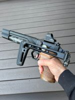
Unfortunately, I'm concerned, from an "anecdotal" observations, that my recent Buck-Rail grip & pic rail conversion, "may" not entirely possess the structural integrity at the spot where a shoulder stock is mounted onto the pic rail. Just as you two indicate, regarding the structural integrity from mounting a stock onto the pic rail block. The design of the Buck-Rail pic rail section, based on my observation after mounting my stock, is in essence free floating and "not" secured to the rear body of the GK1. Of which, presents some torsional and bending forces at the base of the pic rails' connection with the main body of the grip mod (see attached image). Pic #1: using a light under this section, illustrates the gap between the rail & GK1 body without any loading of the stock. The red circle and white arrows denotes where a potential weak point is on the rail, and thereby, with any movement of the rail, appears to stress. And I "surmise", this "may" be where it "potentially" fails - due to a "fulcrum" or "leveraging force" as @Navig.& @TiPascal so apropo theorize. Pic #2: under mild pulling of the stock, you can see that the space in the gap has at least doubled.

Again, please note, I am not a structural engineer and merely expressing my observational hypothesis.

I abhor mentioning any negative commentary about the Buck-Rail grip accoutrements. For the 3D print quality is one of the finest I've seen and laid hands on. I also need to mention their customer service is excellent; and hopeful that any potential subsequent iterations, will address any "potential" structural design defects. The "one off" design and material that @sb327 (Dave) used in his grip mod, IMHO is the way to go and will most likely last the test of time!

In the meantime, I own it and will continue to use it. But feel as if I have to always be cognizant of the amount of torsional movement it exhibits each time I deploy the folding stock during use. Not a fully comfortable position to be in. I equate this to the issue we have with the V1 & V2 mag release lever, that requires us to always remember to gingerly close it to avoid snapping it off, whilst under higher pressure levels.

In closing, I believe this would not be a problem, if made out of a durable metal. Or in the least, if the rail sat flush with the rear of the GK1 body AND not be free floating, but secured with the two bolts already located on the rear of the GK1 body. Other than all that, I'm very happy with the Midwest Industries shoulder stock and all its ability to adjust the LOP, cheek riser and shoulder pad!

Buck-Rail potential weak spot.jpg
Buck-Rail potential weak spot 2.jpg


20240419_160218.jpg


20240419_154401.jpg


20240419_160336.jpg
 
Last edited:
Lots of awesome products out there. @Airtillery, send me some measurements and I'll print you a shim if you'd like.


Just to make sure my block worked with off-the-shelf parts, I picked up a 5KU folding stock from evike, and mounted it:


5ku attached.jpg


Works great! Solid in all directions. BTW, it’s a nice stock, works great, super sturdy and lightweight and fairly inexpensive.


HOWEVER--going to try build my own stock!

Stick.jpg


I had this old beat up Atlas hiking stick; the handle has degraded from weathering. Obviously it is sturdy lightweight aluminum tubing; It has held up to my whole body weight and it has an adjustable length mechanism.