• *Effective 3/27/2024 - The discussion of the creation, fabrication, or modification of airgun moderators is prohibited. The discussion of any "adapters" used to convert an airgun moderator to a firearm silencer will result in immediate termination of the account.*
  • The AGN App is ready! Search "Airgun Nation" in your App store. To compliment this new tech we've assigned the "Threads" Feed & "Dark" Mode. To revert back click HERE.

Talon P Moderator Upgrade? Admit Defeat :)

Regarding the rifle itself HERE and HERE
Regarding the moderator itself.

Intro

IMG_20240108_075226203.jpg

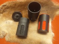
Red is PETG and black is TPU.

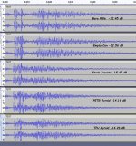
Well now! This is interesting! I do think I shall have to revisit my design. Here are the five test samples, one shot each, 60 ms of each shot. Score is Airforce one, Oldspook zero! 🤪 I am sticking by my opinion though. I should have copied their design but in a new material...

My two designs were LESS effective by a significant margin than the Airforce moderator. The PETG design was 25% worse and the TPU design was 24% worse. TPU was still better than PETG but clearly my design was not up to the task.

TalonP-Upgrade.jpg


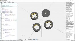
I have already drawn the baffles so that I can duplicate them. Attached is that code for anyone who wants it so that they can test other materials.
AF-TalonP-Moderator-Baffles.jpg
Next update I will copy only the Airforce inserts and retest. Find that here.
 
Last edited:
Previously

I have copied the Airforce baffle stack in TPU and run a quick test this morning. This is proving to be more difficult than I expected. I am going to detail that momentarily, however, I want to address something which may or may not prove out in the accuracy testing down the road. At this point it is s SUSPICION and purely undocumented except for my subjective observations.

Yesterday when testing with the stock baffle stack accuracy was bang on and then the next group would fall apart. Then I'd buckle down and shoot another good group. As I tested it over and over I finally concluded that wind seemed to be opening my groups up. Now I am not saying causing drift, I am saying pellet stability seemed to be an issue when there was a breeze blowing. Normally that rifle is a 3/8" rifle at 25 yards but I had never tested it in moderate (5 to 15mph) winds. I did not observe the same problem with the PETG or TPU design but they were both about a dB louder. You can see that data from the post above.

That said, those observations are not measured they are therefore little more than suspicion at this point.

ONWARD!

Yesterday printing went well and I managed to complete the TPU stack and do some shooting in the evening. Things sounded good and I was hopeful that the gun was now quieter than with the stock baffle set. I went to bed eager to get up and run the test this morning. When I woke it was quite windy. I walked the dogs and made a "wind break" for the camera and got down to testing.

The method was otherwise identical to my normal method and I got results which looked pretty good. I compiled audio of three shot samples for the bare rifle, the stock baffle stack, and the TPU baffle stack.

Here is that information in a graphic.
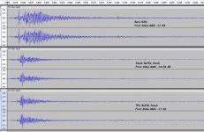
TP-TPU-TEST-@250ms.jpg

How about that?! Still no joy! The stock baffle stack still wins by 0.6 dB. Yesterday the difference between the stock baffles and my TPU design was 24% (about 1.2 decibels) today is is 13%. Now that doesn't seem like much of an improvement but (and this is where dBs are going to bake your noodle) that difference is 3 decibels. Yup. You have to remember the rule if you double the power you have changed it by 3 decibels. It doesn't matter what power you started with only that you doubled it (or in this case halved the difference).

Never the less I still have no joy. Those kids at Airforce did their homework and they have shown me that their choice of material is more absorptive than I thought. Perhaps I could improve upon my material by using a different density? More on that later.

Well if you listen really closely you may be able hear the difference in this audio sample. I can not hear the difference but my ears aren't so good anymore. Three shots each from the bare rifle, the stock baffles, and the TPU baffles. Each shot sampled for a duration of 250ms.


I want to talk a little about the difference between these two moderators so that we can get an idea of the magnitude of difference we are discussing. There is a number I like to calculate when I am comparing moderators. In the past I have called it the "distance to noise floor" and explained that here. I think a better name for that calculation would be the "detectable range". Simplifying the formula by declaring a standard noise floor would be helpful. Here is a chart. You can use when you are making these sorts of measurements with your phone. Your phone uses this scale.

1704811085096.jpeg

When I test I actually measure the noise floor. I don't usually report it because I am not reporting detectable range. Lets look at that number for both moderator stacks I tested today. The noise floor was measured at -44 dB. The bare rifle tested at -11.42 dB. That is a difference of 32. 46 decibels and works out to a "detectable range" of 213 yards if the sensor was at 5 yards. The stock baffle stack was measured at -18.54 dB. That is a difference of 25.46 dB and works out to a detectable range of 95 yards. I told you it was a good moderator ;). Ninety five yards! That is not bad! On a windy morning in the country you are not going to be able to hear this thing at 100 yards! So how good did the TPU do? Well it measured at -17.94 dB (0.6 dB more) and that works out to 101 yards! So there's not a whole lot of wiggle room there. There could be enough measurement error here to invalidate these findings BUT I don't THINK there is. The stock baffle set has consistently been testing better than the TPU. Let's go with that.

Fear not though for I have not given up the effort! Today I will print a couple more baffle stacks in different densities. PERHAPS one of them will improve the performance of the TPU baffle stack. I will link that study here when I have it complete.
 
Last edited:
Weather has been unpleasant. I ran tests anyway.

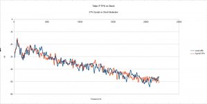
I completed good copies of the baffle set of the Talon in TPU using the Gyroid infill at percentage settings of 25%, 37%, 50%, and 67%. I compared each of those to the bare rifle and the standard baffle stack from Airforce. I have to admit I have not yet cracked that nut. The best baffle stack I made was printed with a 0.6mm nozzle at 37% infill using TPU from Matter Hackers. That stack came to withing 1/10 of 1 dB of matching the factory performance. That's close enough for me to believe additional work on that part of the design is an exercise in futility. I essentially duplicated what Airforce has already done. Well there isn't a whole lot of point to that so.

I tested each of those Gyroid stacks and graphed the results. The graphing suggested an optimal infill density of 36%. I don't see that being enough different from 37% to actually improve the performace much at all and I will continue using the 37% stack for future tests, unless I find a need to print another set.

Here is a graphic of the Airforce baffle stack compared to my baffle stack. For all intents and purposes they are identical.
TP-TPU-TEST-BEST-GYROID.jpg

I have not tested several configuration options which have occured to me and perhaps tomorrow I can get to those. The baffle stack has a central "washer" which can be moved to different places in the "can". There are two possible locations for that washer. One creates two expansion chambers of ROUGHLY the same size. The other enlarges the chamber near the exit and reduces the chamber near the muzzle. We will have a look at that next.

For you printer geeks:
Matter Hackers Build series TPU
Prusa Slicer (standard settings sfor TPU)
** turn off retraction **
Layer Height .36 with a .6 nozzle diameter.
Layer Height .24 with a .4 nozzle diameter.
Gyroid infill density 36% is optimal with .6 nozzle. I'd think 24% would be better with a .4mm nozzle.
 
Last edited:
Today I built some new washers and tested the stock moderator against an optimized Gyroid @37%. I tried several configurations. Nothing worked better. Airforce really did their homework on this moderator. I really am pleased to see an American company delivering good old American engineering. I just wish I could figure out WHY all my Airforce rifles occasionally fart and shoot a shot that is about 3/4 power. That is the most infuriating thing about this platform, you never know when the next pellet is going to be shot with 20% less velocity than the rest of the string. If you have one you can duplicate the problem by leaving the bolt in the middle position after you close it. That should suggest that I've already eliminated that as the cause of that particular issue in my case. But I am wandering...

Anyway I managed to calculate my average standard deviation (testing/measurement errors). That number is about a third of a dB. IOW if I measure it at -19.5 dB the actual value is most probably between -19.8 and -19.2 dB. So not bad. Good enough anyway.

That said, I did confirm my numbers and no I have not managed to find a gyroid density which will consistently out perform the closed cell plastic that Airforce uses. That's good news actually. We have identified two different materials approaches to the same target and they perform to essentially the same level.

This means I am giving up on this effort. The optimum infill density looks like 36% on a 0.6mm print nozzle when I graph the data. I'll be going with that in the future unless specific testing in the specific application suggests otherwise. IOW it is a good starting point for your application.

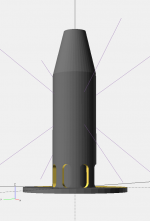
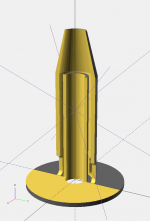
I am now considering what design changes might yield improved performance. I briefly tried adding a cone to the central washer in the baffle stack... no joy. So I came in and drew this:
stock-baffles1.pngstock-baffles2.png

It is running on the resin printer as I write. This is a "reflex" design. It can be inserted into the silencer and provides a stripper (outside cone) which directs air around that core down along the outside of the can through the stock baffle set. That air flow then enters the ports at the bottom and forces it's way to the top of the inside tube where it runs smack into the air trying to follow the pellet out the central tube. Similar to a "Tesla valve", the air being redirected back upon itself. From there pressure is relieved out the side ports on the can and out the muzzle of the moderator.

Will it work? Who knows? But when I run the tests I'll add that data to this post. Maybe tomorrow... maybe in a day or two...
 
Last edited:
  • Like
Reactions: RAMJET66
I got up at "0 dark thirty" with a mission.

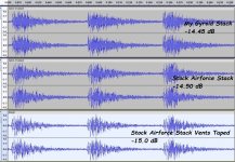
This graph shows the results:
defeated.jpg
My Gyroid stack does not show any improvement over the stock stack. I did not test my stack with the vents taped up and I expect the ratios of performance would remain similar. The Gyroid stack is a very good stack, just doesn't quite match the Airforce stack by a VERY THIN margin.

As a nod to @subscriber I did tape up the holes in that can and test that configuration with the standard stack. I measured about half a dB of improvement and that is statistically significant. IOW it DID improve performance slightly, but you aren't going to be able to hear it.

I have to either keep banging my head against the wall or admit that I can't improve on this baffle stack. But before I make that admission. Let me show you how good that moderator is performing as it ships from the vendor.

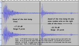
Here is a spectrum trace of that moderator shooting into a Pecan tree at ~20 yards.
tough-to-beat.jpg
I think I covered everything in that graphic. I should have reworded that last sentence though. The sound of the shot contains 1/4 as much power as the sound of the pellet striking the tree.

Here is the audio as it sounded at the microphone for that shot.


Well done Airforce, well done.

TODAY ACCURACY TESTING ;)
 
Last edited:
Some thoughts on gyroid foam:

Would it be useful to stand off a layer of gyroid foam from the ID of the outside wall, so that open space could act as an air capacitor? Yes, we think of the foam as both a flow restrictor and a capacitor (expansion chamber); but I wonder if the full layer depth of the foam acts that way, for a sudden blast of air? A thin layer of foam should be supported at intervals around the circumference for structural integrity.

If the foam layer is thin, then its capacitor function would be limited. If the foam is thick towards the "can" wall, then would air be able to travel all the way through, before air flowing on the inlet side stagnates and tries to flow to a lower pressure area nearby? Thereby wasting some of the potential expansion volume demarcated by the foam.

I am suggesting the primary functions of gyroid foam would be, to act as flow restrictor and internal pressure wave de-bouncer, rather than primarily as an air capacitor or expansion space. Perhaps a thin layer of denser gyroid over a thicker layer of more open gyroid would fulfill all three of these functions, rather than the same density all the way through? (as in anechoic surface, flow restrictor as the air flows in/out f the expansion volume contained in the foam; or behind the foam).

Second point:
I think the Talon foam sections are designed to be easily punched from a foam sheet. So, the lobed pattern at the ID is not very detailed. If manufacturing concerns dominate, is it possible that printing gyroid foam to form a different star patters might work better? Something that could not be punched, because it is too detailed ; and has complex 3D shapes? Perhaps something like the images below.

Now, consider how long and sharp the cones are in some anechoic chambers that don't have to withstand moving air. If the gyroid foam anechoic cones are too thin and pointy, they might not have good durability to withstand air blast. Would it be possible that 3D printing offers an advantage with respect to the ability to make finer "cones" that are also differentiated in shape 3-dimensionally; and durable? For instance, the 45 mm OD pyramidal anechoic baffle shown below.

STL attached in the ZIP file.

If the baffle serves as more than food for thought, but its dimensions are off and cannot be scaled easily to something useful, feel free to suggest better dimensions, and I will edit the file.

View attachment Talon foam anechoic pyramids 45 mm OD.zip

Anechoic baffle1.JPG


Anechoic baffle.JPG
Anechoic baffle5.JPG
Anechoic baffle4.JPG
Anechoic baffle6.JPG
 
Last edited:
STL for version attached below has 6-point pyramids, rather than 9:

View attachment Talon foam anechoic pyramids 45 mm OD 6-point.zip

By the way, the individual rings are 13.4 mm tall - and there are four of them in the stack. That ring height resulted from choosing other dimensions and angles, but can be made shorter or taller. You can have the STEP and / or STL for a modified stack, or a single ring and then stack them yourself, too.

Anechoic baffle 6-point 2.JPG


Anechoic baffle 6-point.JPG


EDIT:
Bob Sterne from the GTA Forum took my baffle spacer STL and created a gyroid infill sliced part from it. With the pyramids denser than the periphery, for greater robustness:

1705376208349.png


1705376242372.png
 
Last edited:
WobblyHand,

The obvious airflow is back to front down the central bore, but the bulk pressure acts in all directions, with a radial component proportional to bulk pressure. If such pressure induced radial flow did not exist, then there would not be any point in making a moderator wider than a straw.

I see the gross topography as an adjunct to the fine texture that the gyroid foam would impart. How well might that work is to be determined. Consider the OEM foam parts with the four rounded lobes. According to OldSpook they work rather well. If such macro shapes did nothing, then a simple foam donut would suffice. So, the OEM part is my inspiration for a non-uniform expansion volume tube.

Air is compressible and rings in all directions inside each expansion chamber, after slamming into the chamber. Not reflecting such pressure waves and damping them out is the name of the game. The design I am proposing has very few surfaces parallel to each other to propagate or amplify what amounts to internal echo. I prefer the 9 sided design, rather than the 6, but include that because the OEM part has an even number of lobes.

I am not claiming anything. I am suggesting something. OldSpook can try it; something similar of his own design; or flat-out ignore the idea. All reasonable choices.
Do you happen to know if the foam parts were aligned, or if they were staggered in some way? Misalignment may make the air do more work, and therefore have more acoustic loss?
 
  • Like
Reactions: OldSpook
I printed a moderator entirely with gyroid and no perimeters. It's not a moderator, although it looks like one! Sound comes out the sides. Yes, I tested it. No structural rigidity. Kind of squishy too. :ROFLMAO:

Printed my latest with gyroid mesh internals but solid exterior walls. Works ok, but I haven't yet been able to take reference audio measurements. Need to print several different variations to try. Printing is the slow part of the process. Waiting for a bigger nozzle to speed things up.
 
  • Like
Reactions: OldSpook
Do you happen to know if the foam parts were aligned, or if they were staggered in some way? Misalignment may make the air do more work, and therefore have more acoustic loss?

My understanding is that the manufacturer recommends staggering their foam rings, so the air path towards the front has more resistance. That is one reason why I staggered the pyramidal cones in my design.
 
Would printing them without the inside wall leaving the gyroid infill exposed work better or worst?

I presume that by "inside wall", you mean the outside perimeter of the gyroid infill? If so, I think that needs to be sealed from the atmosphere by means of something, such as the CF tube the insert is placed into.

If you mean the innermost surface of the gyroid should or should not have a wall or membrane sealing it off, I think the gyroid need to be open for two reasons: So the air in the moderator can see the gyroid (anti-echo) texture; and so air can pass into the gyroid passages (with some friction) to fill it as active air expansion volume.

If neither of these was your meaning, please clarify.
 
  • Like
Reactions: OldSpook
I meant the innermost surface because in my use it would be inside of a CF tube so the outside perimeter isn't needed. So the pyramidal cones facing towards the center wouldn't have any walls just exposed infill. It seems something like this placed inside most of a shroud's length may be beneficial.

Yes, the CF tube ID becomes the aspect that seals the gyroid foam. Earlier I was even suggesting leaving a gap between the foam and CF tube. Either way, the foam might need some reinforcement and location features to center it in the DF tube.

How much benefit micro and macro textured foam would help inside a shroud can be determined via testing. If the shroud volume is small from the start (don't forget the volume lost by the barrel being there), then adding foam might not help at all; if the foam occupies the full length of the rear shroud. But, adding foam ahead of the muzzle in appropriate layer thickness is sure to help. Ditto for near the breechblock end of the shroud. There foam can reduce the bounce of the air that the reflex stripper directed rearwards.

I do think that if the shroud ID is significantly larger than the barrel OD, that having gyroid foam all the way down the shroud in a thin layer could benefit the system. Including less ping from the shroud tube. Just do not block off the space between the shroud ID and the barrel OD with foam. Else, air cant flow backwards suddenly enough on the shot. The last two inches of barrel at the rear of the shroud could probably be filled with gyroid foam, provided it is not too dense.

Again, this is all subject to testing. The results are going to depend on the rest of the system; so benefits obtained with one type, caliber and tune of PCP may not translate to similar results with a different type, caliber and tune. Consider the subject of this thread. OldSpook did not improve on the OEM punched foam discs. I am not suggesting it is impossible; just that we need to temper our expectations. Also, why I am suggesting a different approach. Not because I know it will work. Rather because we have seem this is a tough nut to crack; so a slightly different approach may uncover or discover something useful.

Anyway, OldSpook seems disinterested in the wrinkles we have added to his thread. So, unless someone has pertinent results that OS might appreciate, I suggest we vacate his thread.
 
I printed a moderator entirely with gyroid and no perimeters. It's not a moderator, although it looks like one! Sound comes out the sides. Yes, I tested it. No structural rigidity. Kind of squishy too. :ROFLMAO:

Printed my latest with gyroid mesh internals but solid exterior walls. Works ok, but I haven't yet been able to take reference audio measurements. Need to print several different variations to try. Printing is the slow part of the process. Waiting for a bigger nozzle to speed things up.
 
Thanks. Been lurking on this forum a while, have read the linked thread. (y)